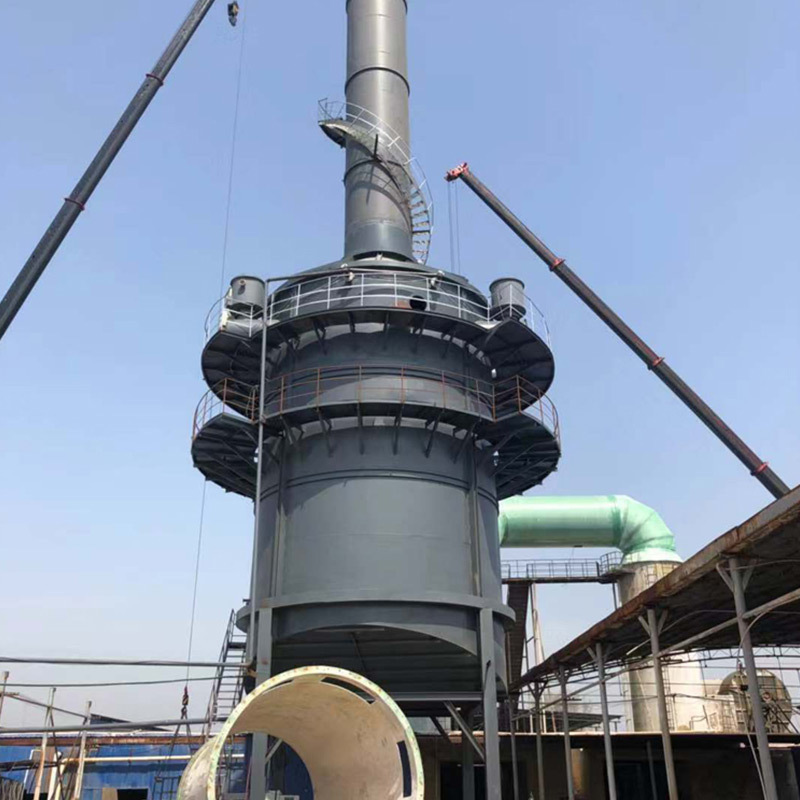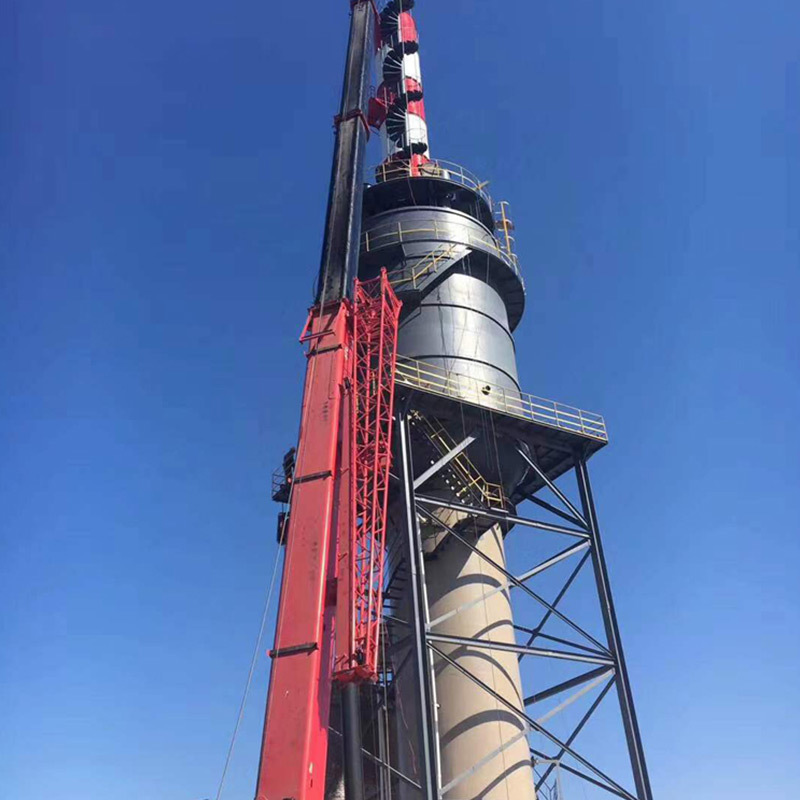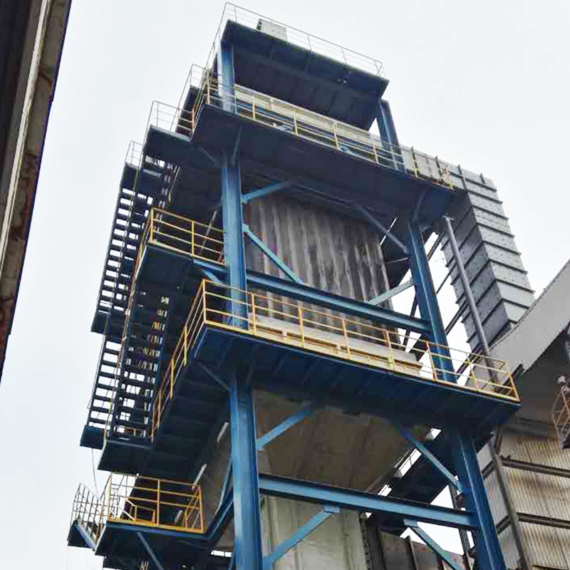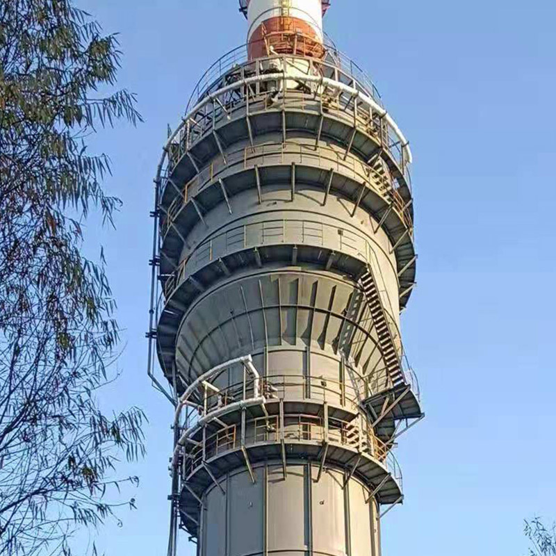


Electrical tar precipitator
- Commodity name: Electrical tar precipitator
- Detailed description
-
Product Description
The electric tar catcher adopts three structural forms: concentric circle, tube, and honeycomb. Regardless of the structure, its working principle is to apply high-voltage direct current between the metal wire and the metal tube wall (or electrode plate) to maintain an electric field sufficient to ionize the gas, forming a corona zone between the anode and cathode.
Structural analysis of this section: The three types of electric tar precipitators are composed of components such as a shell, sedimentation electrode, corona electrode, upper and lower hangers, gas redistribution plate, steam blowing tube (optional configuration), insulation box, and feeding box. The main differences are the form of sedimentation electrode, the arrangement of corona electrode, insulation box, and feeding box.
Scope of Use
The electric tar catcher in carbon plants is mainly used for gas purification in industries such as metallurgy, chemical, coking, carbon, oil shale, blue carbon, urban gas, building materials, ceramics, etc. It is used to recover tar from gas and tar gas, while removing impurities such as dust and water mist, achieving a dual effect of material recovery and gas purification. It plays a crucial role in ensuring the normal and stable operation of equipment in the later stages of the process flow.
Technical Advantages
(1) Stable and highly reliable operation: able to maintain sedimentation efficiency for a long time, able to withstand instantaneous and stable short circuits. When the electric field discharges for some reason, the current output from the power supply of the electric tar catcher is stable, and the current in the electric field does not increase. However, the input current of the power grid is greatly reduced, causing the discharge channel to disappear on its own and not transition to arc discharge. This not only protects the corona wire and anode plate, but also ensures the safety of the power equipment.
(2) The energy-saving effect is obvious: the power factor of the electric tar precipitator power supply is high with a COS ∝ 0.90. Moreover, it does not change with the operating power level, and the output current is basically effective current corona. Therefore, relatively speaking, the energy-saving effect is more significant than other types of power sources.
(3) The circuit structure is concise and easy to operate: due to the modular design of the circuit, debugging and operation are very convenient.
(4) Light weight and small size: Especially for the DC high-voltage generator of the power supply, it has a small volume and light weight. In some places without explosion-proof requirements, the high-voltage generator can be directly installed on the top of the electric field body, eliminating the need for high-voltage cables and dedicated rooms.Technical Parameter
Model
φ×H
Weight (t)
Power Supply
Remarks
FD3-II
Ф0.612×H9.6
1.26
0.05A/60KV
FD7-II
Ф×H 3
0.08A/60KV FD13-II
Ф×H 4.95
0.1A/60KV FD19-II
Ф1.69×H11.18 6.75
0.1A/60KV FD24-II
Ф1.8×H11.2 7.5
0.1A/60KV FD30-II
Ф2×H11.4 7.94
0.15A/60KV FD37-II
Ф2.1×H11.6 8.69
0.15A/60KV FD48-II
Ф2.3×H12.4 10.89
0.2A/60KV FD55-II
Ф2.3×H12.4 10.99
0.2A/60KV FD61-II
Ф2.6×H11.8 12.08
0.2A/60KV FD76-II
Ф2.8×H12.2 13.74
0.3A/60KV FD90-II
Ф3.2×H13 16.54
0.3A/60KV FD102-II
Ф3.4×H13 19.67
0.4A/60KV FD112-II
Ф3.5×H12.6
21.8
0.5A/60KV FD114-II
Ф3.6×H13.2 22.2
0.5A/60KV
FD128-II
Ф3.8×H13.2 24.6
0.6A/60KV FD139-I
Ф4.3×H15.2 32
0.6A/72KV Tapered FD144-II
Ф4×H13.4 26
0.6A/60KV FD160-II
Ф4.2×H13.6 28
0.6A/60KV FD196-II
Ф4.6×H13.8 32
0.8A/60KV FD220-II
Ф4.8×H14 39
0.8A/60KV FD248-II
Ф5×H14.2 43.2
1A/60KV FD276-II
Ф5.2×H14.2 45
1.2A/60KV FD324-II
Ф5.68×H15 58.5
1.4A/60KV FD348-II
Ф5.8×H14 61.2
1.4A/60KV FD400-II
Ф6.128×H16.1 75
1.6A/60KV FD420-I
Ф8×H13.6
1.5A/72KV FD400-II
Ф6.1×H14.1 65
1.6A/60KV
Tapered FD428-II
Ф6.25×H13.2 68
1.6A/60KV FD428-I
Ф7.8×H13.2 1.6A/72KV FD452-II
Ф6.7×H14.2 73
1.8A/60KV FD460-II
Ф6.8×H14.2 79.6
1.8A/60KV FD468-II
Ф6.8×H15.8 82.5
1.8A/60KV Tapered
FD480-I
Ф8.2×H13.2 1.8A72KV FD484-II
Ф6.95×H14.1 81.2
1.8A/60KV FD532-II
Ф7×H15.58 83.6
1.8A/60KV FD572-I
Ф8.6×H14.2 101.6
1.6A/72KV FD696-I
Ф9.5×H14.52 136.8
1.5A/72KV×2 FD700-II
Ф7.95×H14.55 118.4
1.5A/60KV×2 FD784-II
Ф8.25×H14.55 147.5
1.5A/60KV×2
key word:
Get a quote


